.webp)
 EAS Security
EAS Security
.webp) EAS Gate
EAS Gate
.webp) Security Tag
Security Tag
.webp) EAS Accessories
EAS Accessories
.webp) Gadgets
Gadgets
.webp) Convex Mirror
Convex Mirror
.webp) Road Barrier
Road Barrier
.webp) Burglar Alarm
Burglar Alarm
.webp) Calling System
Calling System
How to Use VERBEX Wireless Hospital Calling System – Installation, Setup & Operation Guide
September 30, 2026
How to Use VERBEX Wireless Hospital Calling System – Installation, Setup & Operation Guide
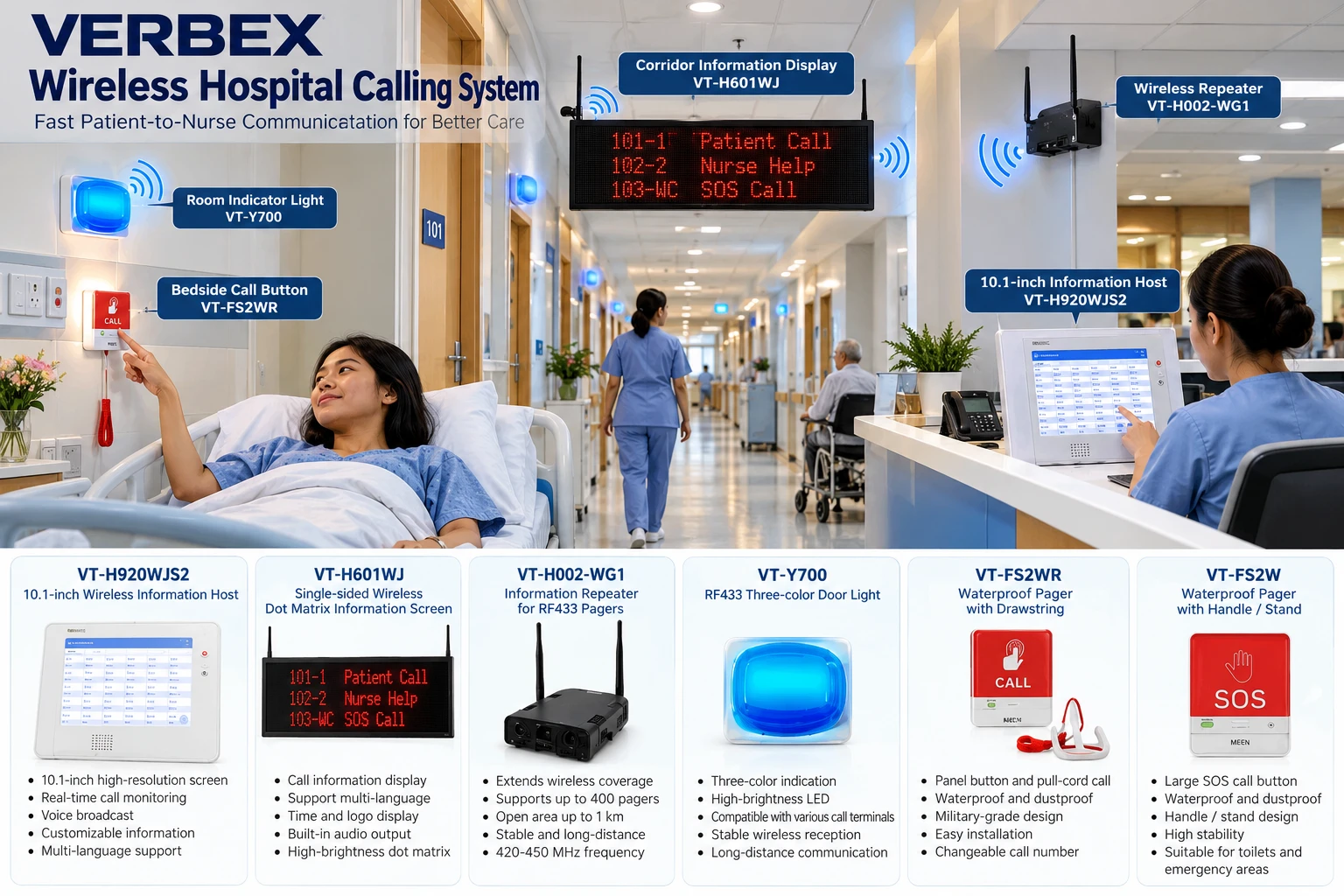
The VERBEX Wireless Hospital Calling System is designed to help patients quickly request assistance while allowing nurses and hospital staff to receive, identify, display, and manage calls from different rooms, beds, toilets, and care areas.
A complete VERBEX hospital calling solution can include the following devices:
- VERBEX VT-H920WJS2 – 10.1-inch Wireless Information Host
- VERBEX VT-H601WJ – Single-sided Wireless Dot Matrix Information Screen
- VERBEX VT-H002-WG1 – Information Repeater for RF433 Pagers
- VERBEX VT-Y700 – RF433 Three-color Door Light
- VERBEX VT-FS2WR – Waterproof Pager with Drawstring
- VERBEX VT-FS2W – Waterproof Pager with Handle / Stand
Together, these devices create a wireless patient-to-nurse communication system for hospitals, clinics, nursing homes, rehabilitation centers, elderly-care facilities, diagnostic centers, and other healthcare environments.
How the VERBEX Hospital Calling System Works
The basic communication process is:
Patient Call Button → Wireless Signal → Repeater if required → Main Information Host → Corridor Display / Door Light → Nurse Response
For example, when a patient presses the VT-FS2WR call button beside the bed, the system sends a wireless call signal.
The call is received by the VT-H920WJS2 Wireless Information Host at the nurses' station. At the same time, the call information can appear on the VT-H601WJ dot-matrix display, while the VT-Y700 three-color door light provides visual indication outside the corresponding room.
For larger hospitals, a VT-H002-WG1 repeater can be installed to extend wireless communication coverage.
Step 1: Plan the Hospital Calling System
Before installation, create a simple map of the hospital.
Identify:
- Patient rooms
- Patient beds
- Nurses' stations
- Toilets and bathrooms
- Hospital corridors
- Emergency areas
- ICU or recovery rooms
- Reception areas
- Areas with thick walls or weak wireless coverage
Each call point should have a unique room, bed, or device number.
For example:
Room 101 – Bed 1
Room 101 – Bed 2
Room 102 – Bed 1
Room 103 – Toilet
Room 104 – Emergency Call
This makes it easier for nurses to identify exactly where assistance is required.
Step 2: Install the VERBEX VT-H920WJS2 Main Information Host
The VT-H920WJS2 10.1-inch Wireless Information Host works as the main monitoring and management terminal.
It is normally installed at:
- Nurses' station
- Main nursing desk
- Hospital reception
- Central monitoring room
- Care-center control room
Main functions
The host can support:
- Real-time call monitoring
- Call-status display
- Customized call information
- Customized screen background
- Customized voice-broadcast information
- Logo and standby image display
- Time display
- Large-screen protocol connection
- Third-party server connection
- Different application-frequency settings
The specification sheet indicates an operating frequency range around 420–450 MHz, depending on configuration.
Recommended installation position
Install the host where staff can clearly see and hear incoming call notifications.
Avoid placing the device:
- Behind large metal objects
- Inside closed metal cabinets
- Directly beside powerful electrical equipment
- Near strong sources of RF interference
A central position usually provides better wireless communication.
Step 3: Configure Room and Bed Numbers
Every wireless call button should be assigned an identification number.
For example:
| Location | Suggested ID |
|---|---|
| Room 101 Bed 1 | 101-1 |
| Room 101 Bed 2 | 101-2 |
| Room 102 Bed 1 | 102-1 |
| Room 102 Toilet | 102-WC |
| Room 103 Bed 1 | 103-1 |
The exact programming procedure depends on the system configuration supplied with the devices.
After programming, test every button individually.
When the patient presses the call button, the correct location should appear on the main host.
Step 4: Install the VERBEX VT-FS2WR Patient Call Button
The VERBEX VT-FS2WR Waterproof Pager with Drawstring can be installed beside a patient's bed or in areas where a pull-cord calling option is useful.
It supports two calling methods:
1. Panel button call
The patient presses the CALL button.
2. Pull-cord call
The patient pulls the attached cord to request assistance.
The pull-cord function is particularly useful for patients who may have difficulty reaching a wall-mounted button.
Recommended locations
VT-FS2WR can be considered for:
- Patient beds
- Toilets
- Bathrooms
- Disabled-access areas
- Elderly patient rooms
- Rehabilitation centers
- Assisted-living rooms
The specification describes the unit as having an ABS shell with waterproof, dustproof, and shock-resistant construction.
Step 5: Install the VERBEX VT-FS2W SOS Call Unit
The VERBEX VT-FS2W Waterproof Pager with Handle / Stand provides another patient-call option.
Its large red SOS area makes the purpose of the unit easy to recognize.
It can be used in locations such as:
- Hospital bathrooms
- Patient rooms
- Elderly-care facilities
- Rehabilitation areas
- Accessible toilets
- Emergency assistance points
When the patient activates the call, the signal is transmitted wirelessly to the monitoring system.
The hospital should assign every SOS unit to the correct room or location during configuration.
Step 6: Install the VERBEX VT-Y700 Three-Color Door Light
The VT-Y700 RF433 Three-color Door Light is designed to provide a visual indication outside a patient's room.
Install the door light:
- Above the room entrance
- Beside the patient's room door
- In a location visible from the corridor
When a patient sends a call, the door light can provide visual notification for passing nurses and hospital staff.
The specification indicates:
- Three selectable colors
- Four high-brightness LED flash lights
- Compatibility with single-key and multi-key call terminals
- Digital coding technology
- Wireless operation
Hospitals can configure different light indications according to their workflow.
For example, an organization may choose to use different colors for different call conditions, but the exact color assignment should be configured according to the installed VERBEX system and hospital procedures.
Step 7: Install the VERBEX VT-H601WJ Corridor Information Display
The VT-H601WJ Single-sided Wireless Dot Matrix Information Screen provides a larger visual display of call information.
It can be installed:
- In hospital corridors
- At nurses' stations
- Near reception areas
- At ward entrances
- In centralized monitoring areas
The display supports automatic processing and loop display of call information.
It can also show standby information such as:
- Time
- Logo
- General information
The supplied specification indicates support for multi-language information and built-in audio output, with the possibility of connecting an external active speaker.
Example
If a patient in Room 205 calls for assistance, the display could show information identifying that call location.
This helps staff notice calls even when they are not directly looking at the main control terminal.
Step 8: Install the VERBEX VT-H002-WG1 Wireless Repeater
Hospitals can contain many obstacles to wireless communication, including:
- Thick concrete walls
- Elevators
- Multiple floors
- Long corridors
- Fire doors
- Large medical equipment
- Separate buildings
The VERBEX VT-H002-WG1 Information Repeater is designed to extend the communication range of the wireless system.
According to the provided specifications, it supports:
- RF wireless signal relay
- LoRa spread-spectrum modulation
- Approximate open-area coverage of up to 1 km under suitable conditions
- Approximately 400 pager devices
- 420–450 MHz application-frequency configuration
- Learning-code technology
Actual range inside a hospital can be lower because walls, equipment, building materials, interference, and installation position affect wireless performance.
Step 9: Test Every Call Point
Testing is one of the most important stages of installation.
After installation, test each patient-call button one by one.
Test procedure
- Press the patient call button.
- Confirm that the main host receives the call.
- Verify the correct room or bed number.
- Check the corridor display.
- Check the corresponding door light.
- Verify any audible notification.
- Test the system from the furthest hospital rooms.
- Test bathrooms and emergency call points.
- Test areas located behind thick walls.
- Verify repeater performance where installed.
Keep a commissioning checklist for every room.
Step 10: Train Nurses and Hospital Staff
The system works best when staff understand what each notification means.
Training should include:
- How to recognize incoming patient calls
- How room and bed numbers are displayed
- How emergency calls are differentiated
- How to respond to calls
- How to clear or reset calls
- What different indicator lights mean
- What to do if a device stops responding
- Who should be contacted for technical support
Hospitals should also establish an internal response policy for patient calls.
Example Patient Call Workflow
Consider a hospital patient staying in Room 305, Bed 2.
The patient requires assistance.
Stage 1
The patient presses the VERBEX call button.
Stage 2
The call button sends the wireless signal.
Stage 3
If the room is far from the nurses' station, the VT-H002-WG1 repeater can relay the signal.
Stage 4
The VT-H920WJS2 host receives the call.
The nurses' station can identify the call location.
Stage 5
The VT-H601WJ display shows the corresponding call information.
Stage 6
The VT-Y700 room indicator provides a visual indication outside the patient's room.
Stage 7
A nurse goes to Room 305 and assists the patient.
The call can then be cleared or reset according to the configured system procedure.
Recommended Hospital System Layout
A typical installation may look like this:
Patient Room
VT-FS2WR / VT-FS2W
Patient presses the call or SOS button.
↓
Room Entrance
VT-Y700
Door light provides visual indication.
↓
Wireless Network
VT-H002-WG1
Repeater extends communication where necessary.
↓
Corridor
VT-H601WJ
Large display shows call information.
↓
Nurses' Station
VT-H920WJS2
Main host receives and monitors patient calls.
How to Use the System During Daily Hospital Operation
Once installation and configuration are completed, normal operation is straightforward.
Patients use the call button only when they require assistance.
Nursing staff continuously monitor the central information host and other notification devices.
When a call appears:
- Identify the room or bed.
- Confirm the type of notification.
- Respond to the patient.
- Provide required assistance.
- Clear or reset the call according to system configuration.
- Confirm the system returns to normal standby operation.
Wireless Coverage Recommendations
For better reliability:
- Install the main host in an open location.
- Keep antennas away from large metal surfaces.
- Do not hide repeaters inside metal enclosures.
- Test the system with doors closed.
- Test all floors independently.
- Install additional repeaters where signal reliability is insufficient.
- Avoid placing radio devices immediately next to equipment producing strong electromagnetic interference.
A professional site survey is recommended for large hospitals.
Maintenance Guide
Routine maintenance helps keep the nurse-call system reliable.
Daily
Hospital staff should visually check important call terminals and the central monitoring host.
Weekly
Test several call buttons from different hospital areas.
Monthly
Test every call point, including:
- Patient rooms
- Toilets
- Bathrooms
- SOS points
- Corridor displays
- Door lights
- Wireless repeaters
Periodically
Check:
- Power connections
- Device mounting
- Wireless communication
- Physical damage
- Pull cords
- Call buttons
- Screens
- Indicator lights
- Antennas
- Device numbering
Any damaged emergency-call device should be repaired or replaced promptly according to the facility's maintenance policy.
Troubleshooting
Call Button Is Not Showing on Main Host
Check:
- Device power
- Device registration
- Assigned identification number
- Wireless coverage
- Repeater operation
- Distance from the main host
- Possible radio interference
Move closer to the host and test again.
If the call works at a shorter distance, additional repeater coverage may be required.
Wrong Room Number Appears
Check the programmed call-button ID.
The transmitter may have been assigned to the wrong room or bed.
Door Light Does Not Operate
Check:
- Device power
- Pairing/configuration
- Room assignment
- Wireless signal
- Indicator configuration
Corridor Display Does Not Show Calls
Verify:
- Display power
- Communication settings
- Address configuration
- Main host connectivity
- Wireless reception
Some Rooms Have Weak Wireless Communication
Consider installing or repositioning the VT-H002-WG1 repeater.
Important Installation Considerations
A hospital calling system can be involved in patient-assistance workflows, so installation should be treated as a professional communications project rather than simply mounting wireless buttons.
Before deployment, verify:
- Local electrical requirements
- Local RF-frequency regulations
- Hospital safety procedures
- Required backup power
- Emergency-response workflow
- Device compatibility
- Building coverage
- System capacity
- Manufacturer installation requirements
The exact setup, programming, pairing, reset, and acknowledgment procedure should follow the technical manual supplied with the installed VERBEX hardware and firmware version.
Where the VERBEX Hospital Calling System Can Be Used
The system can be configured for different healthcare environments, including:
Hospitals
For patient-bed calling, nurses' stations, wards, and bathrooms.
Clinics
For patient-to-staff communication.
Nursing Homes
For elderly residents who may require rapid assistance.
Rehabilitation Centers
For patients with mobility limitations.
Elderly-Care Centers
For bedroom, bathroom, and emergency calling.
Diagnostic Centers
For patient-assistance and room-calling workflows.
Disabled-Care Facilities
For accessible emergency-call points.
Benefits of a Wireless Hospital Calling System
A wireless architecture can reduce the need for extensive communication cabling compared with some traditional wired installations.
Depending on the project design, advantages can include:
- Faster deployment
- Easier system expansion
- Flexible placement of call buttons
- Centralized patient-call monitoring
- Corridor call visualization
- Room-level visual indication
- Extended wireless coverage through repeaters
- Easier addition of new call locations
- Waterproof calling options for bathrooms and care areas
Frequently Asked Questions
What is the VERBEX Hospital Calling System?
It is a wireless communication system that allows patients to send assistance requests to nurses or hospital staff through patient call buttons and SOS devices.
Which device works as the main controller?
The VERBEX VT-H920WJS2 10.1-inch Wireless Information Host functions as the primary monitoring and information terminal in the system configuration shown.
Can calls be displayed in hospital corridors?
Yes. The VERBEX VT-H601WJ Wireless Dot Matrix Information Screen is designed to display call information and other configured content.
Can the system work in a large hospital?
A repeater such as the VT-H002-WG1 can be used to improve wireless communication coverage. Actual system design should be based on a site survey.
Is there a waterproof patient call button?
The supplied documentation describes both the VT-FS2WR and VT-FS2W as waterproof call devices.
Can patients call using a pull cord?
The VT-FS2WR supports both a panel button and a pull-cord calling method according to the provided specification.
What is the purpose of the VT-Y700 door light?
It gives hospital staff a visual indication associated with a patient-room call.
Where should the main host be installed?
Usually at the nurses' station, control desk, reception, or another continuously monitored location.
Conclusion
The VERBEX Wireless Hospital Calling System provides a structured method for connecting patients with nurses and other healthcare staff.
Using the VT-H920WJS2 central information host, VT-H601WJ corridor display, VT-H002-WG1 wireless repeater, VT-Y700 door light, and VT-FS2WR / VT-FS2W patient call buttons, healthcare facilities can create a centralized wireless call-notification network.
For the best performance, every call point should be properly numbered, registered, tested, and documented before the system is placed into operational use. Large hospitals should also carry out a wireless coverage survey to determine the correct number and position of repeaters.